→ 日本語(5軸・複合加工機の誤差計測・補正システム『空間キャリブレータ』)
Error measurement and correction system for 5-Axis and Multi-Axis machines
It is important to adjust the pivot center to ensure accuracy of the 5-Axis machines, which provides with 2 rotary axes such as AC-Axis in addition to the straight XYZ-Axis."SPACE CALIBRATOR" is an automatic error measurement and correction system. It adjusts the accuracy of 5-Axis machines, which is complex and difficult to do manually. "DATABASE ERROR CORRECTION" method enables to compensate the error that was difficult to do by conventional method.
Q. Why it is difficult to adjust the accuracy of the 5-axis machining?
A. Because various factor of errors are piled.
| After mechanical adjustment |
After electric adjustment |
|
|---|---|---|
| Straightness error of XYZ-Axis | 0.005 | 0.005 |
| Perpendicularity error of XYZ-Axis | 0.010 | 0.010 |
| Pitch error of each axes | 0.020 | 0.010 |
| Gap between A-axis center and C-axis center | 0.010 | 0.010 |
| Inclination of AC-Axis | 0.020 | 0.020 |
| Gap between AC-Axis center and XYZ-Axis origin | 0.050 | 0.010 |
| TOTAL | 0.115 mm | 0.065 mm |
Various factor of errors are piled up even if the errors are adjusted individually.
A. Because the error is enlarged when the machining point is away from the pivot center.
0.01deg error of A-axis in angle is enlarged to;
⇒ 0.044mm error in length at a point 250mm away from the pivot center.
⇒ 0.070mm error in length at a point 400mm away from the pivot center.
Q. Is this the limit of the accuracy of the 5-Axis machining?
A. "SPACE CALIBRATOR" enables to correct error piled by various factors.
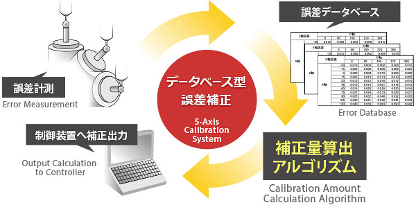
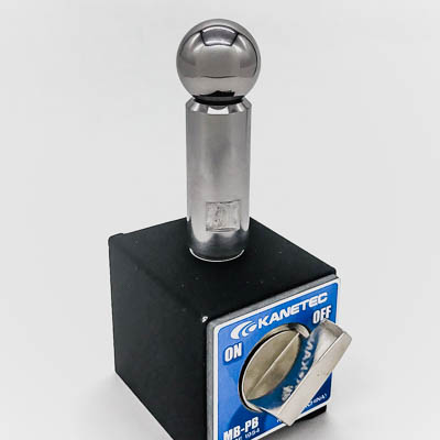
- Measure the positioning error in XYZ direction at each angle of the AC-Axis with a touch probe fixed on a spindle and a datum ball fixed on a table.
- The positioning error measured in XYZ direction is stored in macro variables as an error data base.
- The amount of the error in the XYZ direction is read from the database and corrected at every time the AC-Axis indexes.
* The error measurement and the correction are done with the macro program.
* This is an example that the straight axes are called XYZ and the rotary axed are called AC.
* The axis name and the amount of the error may be different from an actual value.
DATABASE ERROR CORRECTION
The 5-Axis machines equipped with 2 rotary axes in addition to 3 straight axes of XYZ, or the Multi-Axis machines equipped with 2 spindles or more, are able to machine complex shape.
However, the source of error increases, when the number of control axes increases. A lot of factor of errors, such as the straightness error, the perpendicularity error, the parallelism error, the pitch error, and origin error of the each axes are piled, and the accuracy of work piece is decreased.
"DATABASE ERROR CORRECTION" is a new method to compensate errors. It records the positioning error at each point as an error database, and calculates the amount of the correction from the data base. This system compensates the error piled by the various sources, and improves the accuracy of work piece.
FEATURE: All error information on the measured points is effectively used - High Accuracy -
● CONVENTIONAL METHOD
- 24 points are measured as positioning error.
- 1 point is recorded as a center point of rotation. (Most error information is lost.)
- Work zero point is calculated from the center point of rotation.
● DATABASE ERROR CORRECTION
- 24 points are measured as positioning error.
- 24 points are recorded as a error database.(All error information is effectively used.)
- The error is calculated from the database, and corrected.
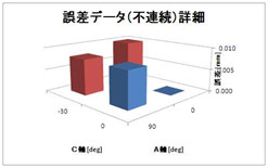
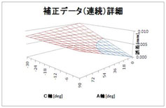
FEATURE: Accurate correction by small database - Practical Method -
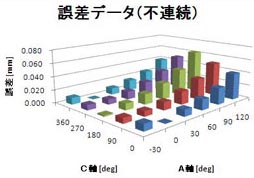
The positioning error of the measurement points are recorded in the database. (Discontinuous Data)
⇒ Short measuring time
⇒ Small database
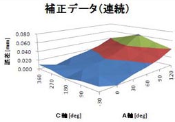
Interpolate the adjoining error data and calculate the amount of the correction. (Continuous Data)
⇒ Accurate correction
It is a Practical System that enables accurate correction even with small database.
It is a Practical System that is able to use rough and exact measurement, according to the area of the stroke.
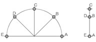
* This is an example which 6 points of A-Axis and 4 points of C-Axis are used as the measuring points.
* Axis name and the number of the measuring points may be different from an actual value.
DATABASE ERROR CORRECTION - Correct the error that is not possible to be analyzed by geometric calculation -
”GEOMETRIC ERROR CORRECTION” method is used in the conventional system with rotary axes. It calculates the position of work piece based on the centre point of rotation, the distance from the centre point, and the angle of rotation. A simple geometric model is enough to correct simple error of center point of rotary axes.
However, a very complex geometric model is necessary to correct the error such as inclination of the center line or the bend by unbalanced weight. This is not a practical method in these cases.
"DATABASE ERROR CORRECTION" records the positioning error in each angle of the rotary axes as an error database, and calculates the correction amount from the database. It is suitable for correcting complex error.
| GEOMETRIC ERROR CORRECTION |
DATABASE ERROR CORRECTION |
|
|---|---|---|
| Simple error (Center point of the rotary axis) | ○ | ○ |
| Complex error (Inclination of center line) | × | ○ |
| Error piled by various factor | × | ○ |
| Error data storage capacity | ○ | △ |
Example1. Center point of the rotary axis
Simple geometric model
⇒ GEOMETRIC ERROR CORRECTION
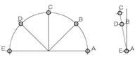
Example2. Inclination of center line (around Y-Axis)
Complex geometric model
⇒ DATABASE ERROR CORRECTION
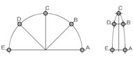
xample3. Inclination of center line (around X-Axis)
Complex geometric model
⇒ DATABASE ERROR CORRECTION
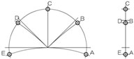
Example4. Bend by unbalanced weight
Complex geometric model
⇒ DATABASE ERROR CORRECTION
DATABASE ERROR CORRECTION - The simple formula has wide range of applications -
“DATABASE ERROR CORRECTION” calculates the correction amount correspond to the position of the reference axes. The formula is liner expression, and the same formula is applicable to rotary and straight axis. It is not depend on the machine configuration, Table-Tilt-Machine or Spindle-Tilt-Machine. This is a Flexible System which is applicable to various machine configurations.
FORMULA of 2 REFERENCE AXES
Error is calculated based on the position of 2-Reference-Axis.
(Example: XYZ-axis is corrected based on AC-axis position)
FORMULA of 3 REFERENCE AXES
Error is calculated based on the position of 3-Reference-Axis.
(Example: XYZ-axis is corrected based on XYZ-axis position)
It is applicable to various machine configurations.
It is applicable to Rotary-Axis or Straight-Axis.

 基準球・基準ボールをお探しの方
 タッチプローブ計測用基準リング
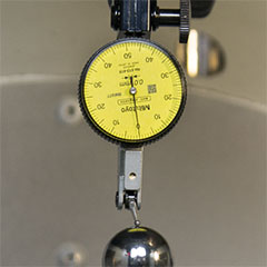 5軸機の心出し計測・精度向上